The Record Table shows columns of data in a table. Append new records to the end of the table, update rows or individual cells by sending commands from your Arduino sketch using RecordTable in our Arduino library. Create a new visualizer by selecting record table from the visualizers menu or toolbox.
Cells in a record table can contain:
- numbers,
- dates, or
- text.
See the Property Table Visualizer for a table that displays name/value pairs.

The Record Table visualizer can be used to display rows of data.
Creating a Record Table Visualizer
Select Record Table from the visualizer menu or toolbox to add a new record table visualizer window to your MegunoLink project. You can add as many record table windows as you like. Use message channels in your Arduino sketch to control the data sent to each visualizer.
Drag the visualizer tab to organize the windows in your MegunoLink project.
Record table controls can also be added to interface panels.
Sending Data from an Arduino
We’ve created an Arduino library to send data from your sketch to a record table visualizer. After you install the Arduino library,
- Add
#include "MegunoLink.h"to the top of your Arduino program, - Create a
RecordTablevariable, then - Call
AddRow, for example, to send a row of data to the table in MegunoLink.
The Arduino record table library reference has details of all the methods available.
The record table visualizer supports Message Channels, a short text string to select the visualizer that RecordTable are sent to. Message channels let you have several record table visualizers in your MegunoLink project and send different data to each.
This example reads 4 analog channels and sends the measurements to MegunoLink. It uses our ArduinoTimer to make and send the measurements periodically. The special value SpecialParameters::CurrentTime instructs MegunoLink to add your computer’s time to the table.
|
1 2 3 4 5 6 7 8 9 10 11 12 13 14 15 16 17 18 19 20 21 22 23 24 |
#include "MegunoLink.h" #include "ArduinoTimer.h" RecordTable MyTable; ArduinoTimer TableTimer; void setup() { Serial.begin(9600); } void loop() { if (TableTimer.TimePassed_Seconds(3)) { int Measurement1 = analogRead(A0); int Measurement2 = analogRead(A1); int Measurement3 = analogRead(A2); int Measurement4 = analogRead(A3); int Measurement5 = analogRead(A4); MyTable.AddRow(SpecialParameters::CurrentTime, Measurement1, Measurement2, Measurement3, Measurement4); } } |
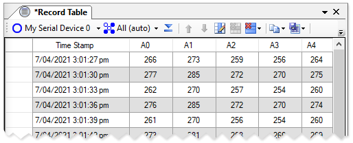
Tabulate data using the record table visualizer.
User Interface
Columns and content are managed using buttons on the record table visualizer toolbar. Edit the content of cells by selecting and typing in the cell. Add a new row by adding content to the last row of the table.
Select the whole table by clicking in the table selector or a row by clicking the table or row selector, respectively. Select multiple rows either by clicking and dragging in the row selector, or selecting the first row and holding down the shift key while selecting the second row. Select non-adjacent rows by clicking the row selector while holding down the control key.
Copy the content of the whole table, or only the selected rows, using the options in the clipboard menu on the toolbar.
Delete or reorder selected rows using the buttons on the toolbar.
The content of the table is not saved in your MegunoLink project file.

Manage and modify the record table visualizer using the toolbar.
Columns have both a display order and a logical order. The display order is the order of columns displayed in the table. The logical order is the internal ordering of columns used when receiving serial data. You can alter the display order without changing the logical order. See logical and display column order below for details.
Adding and Editing Columns
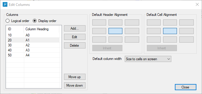
The Edit Columns dialog lets you add, remove, re-order and edit columns. You can set an id for each column, change the column title, width and alignment of content within the column’s cells. Column ids provide a mechanism to reliably send data from your Arduino sketch to a specific column even if the column order is changed in MegunoLink. See AddRowWithIds, for example.
Click the edit columns button (![]() ) on the toolbar to open the Edit Columns dialog.
) on the toolbar to open the Edit Columns dialog.
Add, edit, re-order and delete columns by clicking Edit Columns (![]() ) on the toolbar.
) on the toolbar.
Use the Add, Edit and Delete buttons to add or modify columns in the table. When editing a column you can:
- set the column header, the text that appears at the top of the column,
- a column id, an (optional) number to identify the column when sending data from your Arduino sketch (see logical and display column order below),
- control visibility, an invisible column still receives data but is not shown in the table,
- select a minimum width, for automatic layout, and a maximum width for manual layout,
- set the alignment of text within the column header and data cells. Select Inherit to use the default table alignment.

Column Width and Alignment
The column alignment buttons on the Edit Columns set the default alignment for column heading text and cell text in the table. These default values will be used when Inherit alignment is selected for individual columns.
Columns are resized automatically when new data is received when one of the automatic column sizing modes is selected. Automatic sizing won’t select column widths narrower than the Minimum column width set for individual columns.

The column sizing options available are:
- Size to cells + header: column widths adjust to fit the contents of all cells in the columns including header cells.
- Size to cells only: column widths adjust to fit the contents of all cells in the columns excluding header cells.
- Size to header only: column widths adjust to fit the contents of column header cells.
- Size to cells + header on screen: column widths adjust to fit the contents of the cells displayed, including heading cells.
- Size to cells on screen: column widths adjust to fit the contents of the cells displayed, excluding heading cells.
- Size to cells to available space: column widths adjust so that the width of all columns exactly fill the display area of the table, making sure all column widths are greater than the Minimum column width value.
- None, use fixed column width: column widths are set by each column and do not adjust automatically.
Logical and Display Column Order
Columns in the record table have two orderings:
- logical order, and
- display order.
The display order, the order that the columns appear on the screen, can be changed by dragging columns to a new location in the table.
The logical order doesn’t change when columns position in the table is moved around. It remains consistent so that records received from your Arduino sketch are placed in the correct column even if columns are moved around.


